The project I’ve been working on for some time now is an implementation of a shattering algorithm used to break objects into pieces which could then be plugged to a physics simulation. The technique I went for is so-called Voronoi Shattering because it applies Voronoi Diagrams to generate the fragments, being fairly easy for the artist to define the distribution of those cracks and the overall look.
Shattering a mesh into pieces is an interesting problem that involved a lot more work than I initially thought! – as it is often the case with this kind of geometric algorithms, getting the basic prototype running for easy cases is not too bad, but turning that into a more robust algorithm became 80% of the work. I think it will still be interesting to describe the things that worked along those that didn’t, so I’m splitting this into a couple of posts to keep them manageable.
The problem
Generally speaking, we want to split an object into many solid fragments given by closed surfaces. Provided that we know how to partition the source object, the most immediate problem that arises is that we only have information about the shell of the object, and therefore we must reconstruct the interior volume to figure out how the cracks propagate through that object.
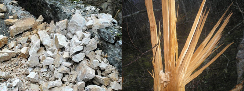
About the breakage process, it’s worth noting that the simulation is itself a very broad subject, and it largely depends on the physical properties of the material we’re simulating: for instance, wereas hard minerals and crystals will generally shatter in clean fractures, other materials such as wood will show some flexibility before breaking, and then splinter off producing a very different kind of fragments. The problem we’re tackling here lies within the first kind of clean-fracturing materials.
The approach: Voronoi Shattering
Purely procedural simulations have little value if they can’t be controlled. I therefore wanted to work on a solution which, while being automatic, would also give the artist some degree of control about the way the fragments are generated without having to describe each one of them individually.
Before getting into details, let’s have a look at the overall picture of the process to better understand each stage (see Fig. 2): we start with a source polygonal mesh which is sampled to produce a set of seed points directing the slicing. Each seed is turned into a set of planes describing it’s corresponding Voronoi Cell (more on this next) which is used to iteratively slice the mesh. After each split, a hole filling stage adds new faces to the mesh to cover the resulting gap. The process is repeated for all the planes of a seed, for each seed, resulting in a set of convex forms corresponding to the fragments.
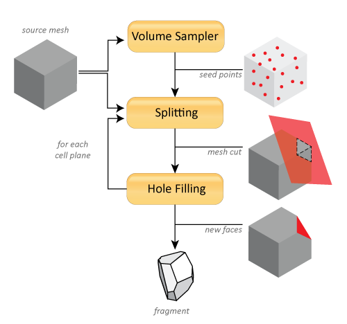
I’ll skip the details about the Volume Sampling for now to avoid sidetracking too much, and leave that (interesting) subject for a further post. For now all that matters is that we start with a set of points related somehow to the mesh we’re breaking – they could be obtained by sampling as it is the case here, but also by using other simpler means such as particle systems. Given those seed points telling us where to break our object, the complex task of splitting the mesh is decomposed into an iterative process of bulding each fragment by splitting the source geometry by a different set of planes each time. Let’s move on to see how we obtain the splitting planes from a seed point by using Voronoi Diagrams.
Voronoi Diagrams
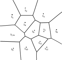
Fig 3. Vornoi Diagram in 2D
A Voronoi Diagram (VD) is a way of decompositing the space which takes a set of points and produces an equal number of disjoint convex areas (called cells), one for each point. A cell encloses the space which is closer to its associated point Si than to any other point of S.
Voronoi Diagrams have many applications, and for our purposes we’re particularly interested in the fact that visually they look a lot like cracks – by tweaking the distribution of the initial set of seed points, we can somewhat control the look of how we’re going to break our object. Furthermore, since we’ll be using the cells to slice the mesh, it is very convenient that there will be no intersections among them, and that each cell is guaranteed to be convex; this simplifies the mesh cutting by allowing us to use infinite split planes.
Delaunay Tetrahedralization
There are algorithms that can generate a Voronoi Diagram directly from a set of points, but a more common way of doing so is by using an intermediate Delaunay Triangulation (DT) of the source points. The graph representing the information of a VD is said to be dual of the corresponding graph of a DT, and vice versa. This means that having one, we have all the information we need to reconstruct the other (for example, the vertices of a DT are the centers of each cell in a VD). Therefore, in order to obtain the VD we can first generate a Delaunay Triangulation from the seed points and obtain the dual graph from it. See Figure 4 for a 2D representation.
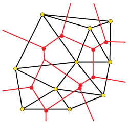
Fig 4. DT (black) / VD (red) equivalence for the set of yellow points
Things get a bit trickier because we’re working on a 3D domain (our points describe a volume), and therefore instead of a 2D triangulation, we require extending the DT to 3 dimensions; this is called a tetrahedralization, since the primitives are no longer triangles but tetrahedra (pyramids with a triangular base). As you probably guessed, an extra dimension to the problem causes an nice evil explosion of new cases to be taken care of!
There is a lot of literature about DT for the 2-dimensional case, being a very well studied problem. However the tetrahedralization doesn’t seem to be so popular, and some of the algorithms available for 2D DT don’t extend to higher dimensions. A good solution would be making use of 3rd party libraries such as CGAL, which it’s really complete and free (in fact it’d be arguably the sensible choice to make) – however, for me the purpose of these pet projects to learn new things, so I took the hard way and went for an implementation of my own :). A good reference I mostly based upon is [Ledoux], which focuses both on the implementation details as well as handling of the (many) degenerate cases of a DT, using an incremental flip-based algorithm.
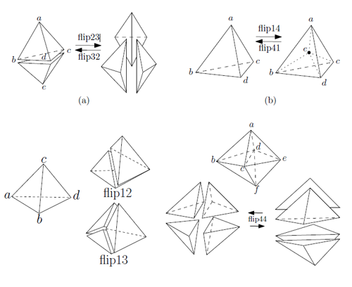
The idea for this mesh tetrahedralization is to start with a single large tetrahedron covering the entire domain, and progressively insert all the points, one at a time. On each insertion, we determine which tetrahedron on the existing partition contains the new point, and split that into smaller tetrahedra (the actual number depends on whether the point lies in the inside of the shape or on one of its faces). The algorithm is called flip-based because after each split follows a neighbour-fixing stage where the adjacent tetrahedra are recursively tested for the empty circumsphere criterion and fixed by flipping them in a series of configurations (Figure 5) until they’re Delaunay. The process is guaranteed to converge eventually, assuming we deal robustly with numerical precision issues. Once we’re done with the Delaunay tetrahedralization, we can easily obtain its dual Voronoi Diagram without further computations.
The cells resulting from the 3D Voronoi Diagram are not actually flat polygons like the ones in Figure 3, but instead convex volumes made up of N-sided faces. An important lesson learnt here is how crucial is getting the DT step right and ensure each tetrahedron produced satisfies the Delaunay Condition (i.e. empty circumspheres) – even slight errors errors in this stage are magnified in the dual VD, resulting in more apparent problems such as cell overlapment or incoherent sizes which will produce horribly-looking cracks.
To be continued…
This is the end of the first part, I hope it was an interesting read! At this point we got all the elements we need to proceed splitting the mesh. In the next post I’ll elaborate about how the fragments are actually generated from the VD cells, and what didn’t turn up that well in the process…
Downloads
I’ve implemented the algorithm as a Maya plugin, there’s a version compiled for Maya 2011 32-bit (Windows) which you can download from here. In the file you’ll find the .mll along with a sample MEL script to set up a sample scene. Please read the license and note this is a prototype to illustrate the described method, rather than a production-ready solution – no technical support is provided. Use it at your own risk (and enjoy it!).
The source code can be found in github
References
[Ledoux] Hugo Ledoux. Computing the 3D Voronoi Diagram Robustly: An Easy Explanation.
hello, I am interested in your project and I download your source code from github. But it seems there’s something wrong with RenderLib, the compiler said many errors. Can you pls help ?
Hi Peng, the project requires the compilation of renderlib and corelib, which need to be pulled as git submodules as explained in https://github.com/joesfer/Voronoi-Shattering/blob/master/README.txt . Please follow the instructions and send me an email to jose [at] joesfer.com if you have issues. Note that the code is provided “as is”, compiled for a now old version of maya 2009 and that it will need to be ported to newer maya versions.
In your README.txt in the shatter.rar, you said it ran successfully on Maya 2011 64bit. Do you mean the code of your version is suitable for Maya 2009 and newer versons ? I am a liittle confused. Because I am total rookie in maya, I am going to install one to play with your shatter code. 🙂
I meant maya 2011 instead of 2009,yes, my bad. The maya API doesn’t really change that much between versions, so it can be a matter of just recompiling.
In fact I was able to compile against maya 2014 for Linux to remove the warnings in Renderlib. However I saw errors when running the resulting plugin on that version – maybe the code has gone stale with the latest libraries, I need to look into it more closely and possibly patch the code on github.
Edit: fixed now, all boiled down to GCC being stricter than MSVC and highlighting extra warnings. Which is a good thing. I got it running on Maya2014 under Linux.
Thanks. Redownload your new RenderLib and CoreLib, these gcc compiling errors disappeared. Now I am trying to play with it. If I have some issues, I will share with you.:-) Many thanks for your quick response.:-D